
|
|
IntroductionWhen it comes to the casting of sugar propellants, the larger the grain (or rather the mould), the easier it is to cast. A small diameter grain, such as that for the A-100M motor, can be quite tricky to cast. The reasons? For one thing, the sugar propellants are quite viscous and generally do not pour well. As such, the casting process is a combination of precise pouring, hurried scooping and careful packing. Secondly, a smaller quantity of melted propellant slurry cools more quickly, and as it cools it becomes even more viscous and difficult to work with. And the sticky nature of these propellants doesn't help matters much. The challenge, therefore, becomes one of getting all the slurry into the mould and done so quickly and without making a mess of the whole thing (which I have done enough times).After a lot of experimentation that resulted in many rejected grains, I've gradually developed a process that works reasonably well. Even so, a lot of practice may be needed in order to finally get the "perfect" grain. In addition to detailing the grain casting process for the A-100M motor, this page describes a means of checking the grain to help determine if the casting is "sound", that is, without bubbles, voids or excessive porosity. The process of coating the finished grain with an "ignition aid" is also described. SuppliesThe following is a list of the supplies required for preparing the mould and for casting the grain
Casting TubeThe casting tube serves as a non-stick liner for the female mould. It also serves to reduce the diameter of the cast grain such that the grain is a loose fit within the motor. Fabricated from tagboard (file folder paper), it is a thin walled tube that is internally coated with grease. The propellant is cast directly into the casting tube. After curing, the casting tube is peeled away from the propellant grain.Materials required
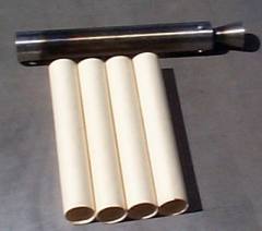
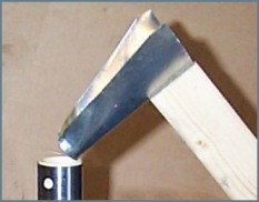
Mould AssemblyThe casting mould assembly consists of the female mould and the mould base, onto which the female mould is mounted. The A-100M motor serves as the female mould. To prepare the motor for use as the mould, a light layer of grease is applied onto the nozzle convergent area (to prevent the propellant from bonding). The nozzle is assembled to the casing (no o-ring is needed). The casting tube is next fully inserted into the casing. A small quantity of 5-minute epoxy is next prepared. A small dab is placed onto the casting tube through the two bulkhead attachment holes in the casing. This is a "temporary joint" which serves to prevent the casting tube from being hydraulically forced out of the casing when the propellant slurry is compressed during the casting operation.The mould base is constructed from a suitable piece of wood through which a wooden or metal closing rod protrudes. When the mould is mounted on the base, the closing rod protrudes partially into the nozzle throat, and serves to block the propellant slurry from exiting through the throat. The rod needs to be a slightly loose fit in the throat to allow trapped air to escape during the casting procedure. As such, the closing rod is made from 1/4" (0.635 cm.) diameter material, slightly smaller than the 0.267" diameter nozzle throat. Also to facilitate removal of trapped air, a number of small vent holes are drilled in the base around the closing pin. The closing pin should protrude exactly half way up the throat, a distance of 1.57 in. (4.0 cm) above the base. The motor is placed onto the base over the closing pin, and then hot glue is applied around the periphery of the nozzle to temporarily secure the motor in place. Click here for a diagram of the mould assembly. FunnelI have experimented with various means of channeling the slurry efficiently into the mould, including open funnels and closed funnels. The method that works the best for me is the open funnel. It consists of a trapezoidal shaped piece of sheet metal (galvanized steel or aluminum work well) or other heat-resistant material that will hold its shape when bent. The sheet is formed by bending approximately into a shape that is best described as a semi-cone, likened to a cone that is split in half along its length. Mounted with a couple of screws onto a wooden handle, it is supported (in a vise or with suitable clamps) at a 45o angle, with its spout directed over the mould.
Click here for a diagram of the funnel. Coring Rod & PlungersThe coring rod serves as the "male mould" that forms the central circular core of the propellant grain. It is inserted into the molten slurry and left in place until the propellant cools and sets. There are two plungers that I use in the casting process, a solid plunger and a hollow plunger. Both plungers are fabricated from metal. The solid plunger, which is simply a circular rod of 3/4" (20 mm) diameter, is used to press the molten slurry down after it is loaded into the mould. The hollow plunger, which is of a diameter just slightly less than the mould, is used to compress the slurry and squeeze out any air bubbles that may be present in the molten propellant. The hole through the hollow plunger is required to allow it to slide over the coring rod, as this plunging operation is performed after the coring rod has been inserted.Click here for a diagram of the coring rod and plungers. Casting the grainPrior to casting:
Next, using the hollow plunger, slide it over the coring rod and press down on the propellant in order to give it a final packing. Hold onto the end of the coring rod to prevent it from being forced out by the pressure. Do not press excessively hard on the plunger. Withdraw the plunger most of the way from the mould, but leave it partly inserted to ensure the coring rod remains centered. Allow the propellant to adequately cool before disassembling the mould, typically 30-45 minutes for KNDX and 60-75 minutes for KNFR. KNSB, however, must be allowed to cool and cure for 24 hours.
Table 1 -- Recommended casting temperatures Use a hairdryer to soften the hot glue that bonds the nozzle to the mould base. The coring rod is removed by firmly gripping the protruding end in a vise or with locking pliers. The female mould is then slid off. The grain is then grasped and given a quick rotational twist. This will break the weak "bond" between the coring rod and the propellant, allowing the coring rod to be pulled out. The casting tube is carefully slit lengthwise then peeled off. Grain FinishingAt this point, the propellant grain will have a thin residual coating of grease on the outer surface and on the surface of the core. This must be cleaned off completely to prevent delayed or failed ignition. This can be accomplished with the use of acetone or lacquer thinner. As well, the grain may be somewhat sticky to the touch. This is a consequence of residual moisture that had been present in the propellant mix. The heat from casting "forces" the water vapour out of the propellant. This moisture then gets trapped at the interface with the casting tube. The propellant can be dried by placing the grain in a dessicator. This is simply a sealed container (e.g. tupperware) with a layer of calcium chloride, silica gel, or other chemical dessicant (usually in the form of pellets) present. The pellets should not contact the propellant grains, else the pellets will tend to dissolve and stick to the grain. For long term storage, a dessicator should not be used. There is evidence that suggests that the grain get overly dry, the result of which may be a burn rate greater than normal. This could result in a CATO. For long term storage (if required) the grains are best placed into a zip-lock bag then placed into a freezer.After cleaning, the grain may be trimmed as required, then the grain mass and dimensions should be recorded. The key dimensions are shown in Figure 4.
 A mass density check is recommended. Using the measured dimensions, the grain volume is calculated. The mass density is given by the grain mass divided by the grain volume. This density is then compared to the ideal mass density. The ideal mass density is that of a "perfect" grain with no trapped air, inclusions, surface flaws, or other imperfections that affect the grain volume. The method of calculating the grain volume and density is provided in Appendix A. For convenience, an Excel spreadsheet has been created to help perform the density check. This spreadsheet also provides the ideal density for a wide variety of sugar propellants, including those doped with oxides or other ballistic modifiers. Grain Density Check (GDC) spreadsheet: Graindensity.xls I've typically obtain grain densities of 95% ideal using the casting method described here. If the measured grain density is less than around 90%, this implies significant air inclusion (porosity) or the presence of significant flaws or air bubbles. External air bubbles or flaws can be repaired by opening a cavity then filling it with molten propellant. If the density is less than 90% and no external flaws are apparent, then either hidden voids exist or porosity is present, and the grain should be discarded. The consequence of firing such a grain could result in a CATO due to unpredictable burning rate behaviour. Although a propellant grain may be loaded and fired once it has been dried, for maximum performance, the grain should be painted with a thin coat of Ignition Powder. The preparation of Ignition Powder, which consists of 80% Potassium Nitrate and 20% Charcoal, is described in the Igniters & Ignition Systems webpage. The purpose of this coating is to facilitate rapid ignition of all burning surfaces of the grain. The consequence of such is a nearly instantaneous motor chamber pressure rise to that of the design operating level. This minimizes impulse loss associated with delayed pressure rise. The striking difference between an uncoated and coated grain is illustrated in Figure 5.
To coat a grain, a few grams of Ignition Powder is finely ground up, then mixed with 70% isopropyl alcohol (IPA) such that the consistency is similar to thick paint. A brush is then used to apply a light coating over the entire outer surface. It is not necessary to coat the core. The grain is then allowed to dry for a half hour or so in the open air, and is then placed into the dessicator to complete the drying process. The dried coating is very durable and will not rub off by normal handling or storage.

Appendix A -- Grain Density Calculations
 where  The grain density is given by the mass divided by the grain volume: Units of measure should consistently be grams & centimetres or pounds & inches.
Table A1 provides the ideal mass densities for various propellant formulations, including those doped with red iron oxide (RIO). 
|
