|
|
|
|
HistoryThe idea for the B-200 rocket motor (Fig. 1) was conceived in 1973 (originally as the B-III motor), with the intent of developing a motor utilizing KN-Sucrose propellant that would be used for powering rockets suitable for testing parachute deployment methods. The aim was to boost the rocket to a sufficient height to provide a reliable test of the parachute system, yet not so high that a failure to deploy the parachute would mean total loss of the rocket. A reasonable height was considered to be between 1000 - 2000 feet (300 - 600 metres). Although the B-200 was originally designed for the KN-Sucrose propellant, the substitution of KN-Dextrose propellant has recently been investigated and proven by a successful static test firing and subsequent rocket flight.
 Figure 1 -- B-200 Rocket motor componentsPerformanceThe thrust function for this motor powered by KN-Sucrose is shown in Figure 2a below, achieving a maximum thrust of 260 pounds (1157 Newtons), and a total thrust time of 0.38 seconds. This performance graph was based on results from a static test of the motor (AST-17). The total impulse is 65 lb-sec (288 N-s), which fits it into an "H" class designation. The high thrust combined with a short burn time provides for very quick acceleration of the rocket, which is beneficial for providing rapid aerodynamic stability of the rocket vehicle after departing the launch guide-rod. The propellant grain is "free-standing", which means that it fits loosely within the casing (not case-bonded). Burning is completely unrestricted, such that the grain burns on both inner and outer diametrical surfaces, as well as both ends. This burning characteristic was chosen to avoid structural loading of the grain, as would be the scenario with a case-bonded grain, a particularly important consideration considering the high modulus (stress / strain), brittle nature of the propellant. This motor is capable of boosting a 3 inch (7.6 cm) diameter rocket, with a mass of 4.5 lbs (2 kg), to an altitude approaching 2000 feet (600 metre) (this was typical of the rockets which I launched). If the rocket diameter is reduced to 2 inch (5 cm), the same rocket powered by the B-200 motor would achieve a peak altitude of close to 1/2 mile (0.8 km).  Figure 2a -- B-200 delivered performance graph Figure 2b -- Graph of Kn and propellant web thickness as a function of web regression Figure 2c -- Comparison of theoretical performance for the Sucrose v.s. Dextrose propellantNozzleThe B-200 nozzle is a conical profile, convergent-divergent, supersonic type. It has a 30 degree convergence half-angle, and a 12 degree divergence half-angle, and has an area expansion ratio of 8.0. It is machined from a single piece of hot-rolled (HR) or cold-rolled (CR) mild steel bar stock (typically C1018), with polished inside flow surfaces. Of particular importance is the throat region, being the most critical with regard to motor performance. The nozzle contour is rounded at the throat to avoid sharp discontinuities * in profile. The nozzle has a groove machined around the outer perimeter of the convergent section, to provide a recess for the nozzle retention screws. Six 1/4 inch hi-strength set screws, which engage into threaded holes in the casing, retain the nozzle. The nozzle is not normally removed once installed (propellant is loaded at the head end). To reduce leakage between the nozzle and casing, the casing is rolled around its circumference (after insertion of the nozzle) utilizing a customized tool which effectively reduces the casing diameter locally, providing a nearly gas-tight seal. This tool is essentially the same as a constictor tool, as used in HVAC applications. More recently, coating the nozzle and filling the groove with silicone RTV has been used to further minimize gas leakage. * to reduce shock losses, as well as to provide a more gradual acceleration of the exhaust gases, important to prevent particle velocity lag associated with two-phase flow.  Figure 3 -- Details of B-200 nozzleCasingThe casing is made from seam welded steel tubing, specifically, 1-1/4" Electrical Metallic Tubing (EMT), also referred to as "thin-walled conduit". This particular tubing has the minor disadvantage of being zinc coated, which would tend to blister when the motor is fired, as the exterior casing surface briefly reaches a temperature of about 800 deg.F. (430 C.) at some locations. I generally would turn down the casing (using a metal lathe) to remove the zinc coating, and to reduce the wall thickness to 0.060 inches. This thickness still provides for a safety factor of 1.5 based on hoop stress at MEOP (Maximum Expected Operating Pressure, 1600 psi) compared with the ultimate strength of the material. This wall thickness also ensures no permanent deformation (yielding) of the casing under operating pressure.  Figure 4 -- B-200 Motor casing dimensionsMotor HeadThe motor head (Fig. 5) is basically a pressure bulkhead which, together with the gaskets, serves as a closure to seal the combustion gases within the motor to generate the pressure required to produce thrust. The head is not directly attached to the casing, rather, it is retained by the safety shear pin assembly. It is subjected to the full force associated with the combustion chamber pressure acting over it’s area., and since the shear pin spans across the middle of the head, the head is subjected to bending stresses. To reduce weight, the head is hollowed out at the centre, yet around the perimeter, it is sufficiently thick to act as a piston, and to provide bending stiffness. The head is machined from a piece of cold-rolled (CR) steel bar.  Figure 5 -- Details of B-200 headGasketsThe gaskets, which are installed directly behind the head, serve the important function of sealing the front of motor to prevent excessive gas seepage. The gaskets, of which there are typically four installed, are discs cut from asbestos laden heat-resistant gasket material, of the type used for sealing high pressure, high temperature water pumps. The gasket material has a thickness of 1/16 inch (1.6 mm). These are cut to size of a diameter slightly greater than the inside diameter of the casing, and are carefully installed after insertion of the grain. The gaskets are installed by “dishing” the middle portion (concave downward) into the casing. The head is then installed, pushing the gaskets down such that they butt against the head in the final installed position. In this manner, when the motor pressurizes upon firing, the pressure forces the gaskets flat against the head, subsequently forcing the perimeter edges of the gasket tightly against the casing wall. More recently, coating the gasket perimeter with silicone RTV has been used to further minimize gas leakage. Safety Shear Pin AssemblyThe purpose of the shear pin assembly is to retain the motor head. The safety shear pins are designed to shear at a motor pressure below that required to burst the motor casing. This is to allow for a controlled release of the high pressure combustion gases through the front of the motor if for some reason the pressure gets abnormally high (such a scenario may be a cracked propellant grain or obstructed flow at the nozzle). The pins consist of two Grade 5 (70 ksi shear strength) 3/16 inch diameter machine screws which connect at a threaded coupler.  Figure 6 -- Details of B-200 Safety Shear Pin assemblyPropellant grainThe B-200 motor was originally designed to be powered by KN-Sucrose propellant. More recently, however, KN-Dextrose propellant has been successfully used instead. 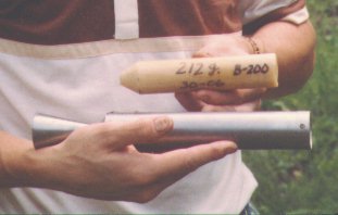 Propellant grain shown with an earlier B-200 MotorLife expectancyDue to the short burn time, and owing to the combustion temperature of the propellant (at 65/35 O/F ratio) being tolerably less than the melting point of mild steel, no erosion of the B-200 nozzle occurs, even though the throat region gets red hot during firing. As such, the B-200 motor nozzle is indefinitely reusable. The motor casing also fares well, with the wall stress being sufficiently below the yield point of the material to avert permanent deformation. Generally, some bearing related damage occurs, over time, at the nozzle retention screws, or at the shear pin holes. As such, I’ve found that the casings needed to be replaced after about ten firings. Due to the highly water soluble nature of the propellant combustion residue, cleaning of the motor is simple, requiring merely a bath in hot water and a brush to scrub away the combustion residue. |

