Introduction
This web page presents the test report detailing the first static test (KSB-001) conducted on the Kappa-SB rocket motor, as well as post-test analysis.Motor details
The motor for this test was the same as that used for the second Kappa static test (KDX-002). The principal difference is the type of propellant, being KN-Sorbitol, rather than KN-Dextrose. Certain modifications were made to the motor:
- The casing thermal liner was a two-layer design. This consisted of an ablative layer of polyester/styrene resin impregnated absorbent paper of thickness 0.020 in. (0.5 mm) bonded to a base of paper insulation, of 0.0165 in. (0.42 mm) thickness. The liner was formed into a tubular shape by first heating in an oven (to soften the resin), then rolling over a mandrel and joining at the overlapping seam with silicone II adhesive. The liner tube was then inserted into the casing (snug sliding fit) such that it would butt up against the nozzle. Silicone RTV was then applied to the tube end, and the nozzle installed. At the forward end, RTV was also used to seal the liner tube end, which extended to within a centimetre of the bulkhead. The short section of exposed casing was coated with silicone grease.
- The propellant inhibitor was similar to that used for KDX-002, consisting of resin soaked fabric. The fabric was lightweight cotton, of 0.008 in. (0.20mm) thickness, and was cut to size to form a single layer around the segments. The process of inhibiting the segments was to first coat the segment outer surface with a layer of polyester/styrene resin, the carefully wrap the resin soaked fabric tightly around the segment. After setting, the inhibitor liner was trimmed and sanded smooth. Final thickness of the inhibitor coating averaged 0.012 in. (0.30 mm). As an extra measure, each liner was then painted with a layer of hi-heat aluminum paint, and lightly coated with silicone lubricant (Castrol Syntec).
The above method was used for 3 of the 4 segments. The third and fourth segments that were made were cast into a liner formed from a different type of paper than the first two (which disbonded). The third segment bonded very well to the liner, and as such, the liner was retained. A second layer of the same "tagboard" material of 0.010 in. (0.25mm) was then bonded (using Silicone II adhesive) to the liner to form a double layered inhibitor. The fourth segment bonded fairly well, but had a few locally disbonded spots. It was decided to remove the liner and use the resin coating method. - The four propellant segments had a total mass of 1508 grams (excluding inhibitor liners) and are shown in Figure 1. Propellant core diameter was 0.75 inch (19.05mm) and O.D. was 2.23 inch (56.6mm). Average segment length was 3.80 in. (96.5mm) and typical O.D. was 2.26 in. (57.4mm). Total grain length, including spacers, was 15.75 in. (400 mm).
- A conventional throat-inserted igniter was used instead of the integral bulkhead canister design. This is to allow for igniter installation to be performed at the test site.
The completed rocket motor is shown in Figure 2.

Figure 1-- Propellant segments

Figure 2--Kappa-SB Rocket Motor. "Strips" are thermal-sensitive labels which darken when exposed to heat.
Static Test Rig
The STS-5000 Static Test Rig was used once again for this test. Both thrust and chamber pressure were measured. Thrust was measured by use of a hydraulic load cell connected to a 4" 0-1000 psi pressure gauge. To measure chamber pressure, the motor bulkhead was tapped with a pressure fitting which was connected to a 4" 0-2000 psi gauge. To prevent damage to the gauge by hot combustion gases, the connecting line was filled with oil (SAE 30). Gauge readings were recorded by use of a video camera located 10 feet (3 metres) away. A plexiglas shield protected the camera from possible debris in case of a motor malfunction. As well, the shield buffered the camera from the shock waves due to the supersonic flow exiting the nozzle during normal operation.The rocket motor and test rig are shown in Figure 3.

Figure 3 --Author preparing to install rocket motor in Test Rig
Test Report
September 9, 2000 -- After assembling the Test Rig at the test site, the motor was installed, connections to the chamber pressure gauge were made, and the oil buffer system was filled. A single video camera was used to record the two pressure gauge readings. A 35mm still camera with 135mm telephoto lens and autoadvance was used to record the firing, from a distance of about 100 feet (30 m.). The autoadvance, which was activated just prior to ignition, allowed for continuous shooting of photos at a rate of 2 frames per second.Once the setup was completed, and the observers located a safe distance away from the test stand, the countdown was commenced. The igniter fired immediately after the ignition button was depressed, making a distinctive "pop" sound. Less than a second later, the motor thrusted with a loud sound, and appeared to be functioning well, with a very large and well-shaped smoke plume, which topped at an estimated height of 75 feet (20 m.). The sound of the exhaust jet was steady (no undulations). The strong thrusting continued for about two seconds, then rather slowly tailed off. Blackish smoke then issued from the nozzle, and about a second after burnout, a bright yellow/orange flame erupted, as the vapourized residue in the motor ignited. The flame soon self-extinguished. The spent motor was then quickly approached in order to observe the strips of heat sensitive film. All were black, with the two strips nearest the nozzle end of the casing somewhat blistered from the heat. The motor was very hot to the touch, in particular the nozzle, which was completely blackened (as per the previous two tests). A photo of the motor under full thrust, taken with the 35mm camera, is shown in Figure 4.

Apparatus at right is videocamera for recording gauge readings, protected by plexiglas shield.
Analysis
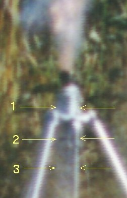
In order to obtain an estimation of how hot the casing got during firing, four strips of "thermal sensitive tape" (Brother M-Tape) had been placed around the casing, as shown in Figure 2. As noted in the test report, the first two strips (nearest the nozzle) were found to be completely blackened, and slightly melted after the test. The third and fourth strip were also black, but were otherwise undamaged. No firm conclusions could be drawn from this alone, since heat from the hot spent motor would rapidly soak through to the casing. Only the temperature of the casing during structural loading (firing) is of consequence. Therefore, the series of photos taken during the actual firing were magnified and closely examined, to see if a blackening of the tape strips could be detected. Indeed, the first 3 strips were visible in the photos. Strip #1 and strip #3 remained white during firing, but strip #2 turned black near the end of the burn (photo). This tape reportedly begins to decompose at a temperature of 365 C. The temperature at which the tape begins to blacken in currently not known. The maximum design (target) temperature was 150 C., so this was clearly exceeded in (at least) the localized area of the casing at strip #2.When the motor was opened up for post-firing inspection, the insulating liner was found to be burned quite severely. In a number of locations, the liner was in fact perforated (see Figure 5). The liner was more severely burned than the previous test (KDX-002) undoubtedly due to the longer burn time. Combustion gases had impinged upon the casing walls at these locations, but upon close examination, it was apparent that no damage had occurred to the casing as a result. Clearly, burn-through must have occurred at the final moments of the firing, allowing the casing to dissipate the heat. The region of the liner that had the most severe burn-through coincided with tape strip #2. Interestingly, the forward portion of the liner had minimal heat damage. This is where the segment with the paper inhibitor was located. This segment was quite snug fitting, unlike the other three which were a loose sliding fit.

Figure 5--Casing and thermal liner, post-test condition
The casing outside diameter was measured at several locations; no permanent deformation was found to have occurred.
The nozzle had no measurable erosion of the throat (< 0.001 in.). The aluminum alloy bulkhead was in good condition, with no heat damage.
The buna O-rings that sealed the nozzle and bulkhead again performed flawlessly. Careful examination of the O-rings confirmed that there was no blow-by whatsoever. The cross-section of the nozzle O-rings, however, was no longer circular, but flattened on two opposing sides, most certainly due to the heat "soaking" in the minutes after burnout.
Performance
Figure 6 shows a plot of the measured thrust and chamber pressure. Note that the pressure gauge line inlet (at the bulkhead) apparently got partially blocked by exhaust residue. Only when the pressure differential between the residual pressure in the gauge line and the chamber got large enough did the blockage get cleared.

Figure 6 -- Actual motor thrust and chamber pressure as a function of time
As can be seen, the two parameters (curves) follow one another closely, as would be expected. Chamber pressure and thrust are related by the following equation:

where F is the thrust, Cf is the thrust coefficient, At is the nozzle throat cross-sectional area and Po is the chamber pressure. The thrust coefficient is an important parameter which relates the amplification of the thrust due to gas expansion in the nozzle as compared to the thrust that would be exerted if the chamber pressure acted over the throat area only. In Figure 7, the thrust coefficient is plotted. The value of the thrust coefficient achieved the target design value of 1.45 only between the 0.9 and 1.4 second marks, which corresponds to the pressure peak.

Figure 7 --Nozzle thrust coefficient, shown over a portion of the steady-state burn regime
From the thrust-time curve, the total impulse of the motor was determined to be 1780 N-sec. (400 lb-sec.), which was less than the design impulse of 2000 N-sec. by 11 percent. The delivered specific impulse was a rather dismal 120.4 sec., suffering (in part) from the low chamber pressure, which had an average of 735 psi. This compares to a delivered specific impulse of 137 sec. for the KN-Dextrose propellant in test KDX-002. The average chamber pressure for that test was 815 psi (5.62 MPa.).
Figure 8 shows a comparison of the actual thrust and pressure curves to the design (predicted) thrust curve.

Figure 8 -- Comparison of actual and design thrust curve
The shape of the thrust and pressure curves are strikingly different than expected. The actual pressure curve (Fig. 6) rises nearly linearly from about 100 psi to the peak. The thrust curve has a similar profile although the slopes (rise and fall) are somewhat concave, and are quite symmetric. The thrust and pressure peaks are both well defined and occur exactly half way through the burn. Curiously, the maximum thrust and maximum chamber pressure are both within 3% of the previous Kappa-DX test results.
Conclusion
The shape of the thrust and pressure curves were much different than predicted. The predicted curve was derived from performance calculations based upon burn rate v.s. pressure data obtained from an extensive series of strand burner measurements . The reason why the curves were of an odd "triangular" profile is not currently understood. It would seem to be a consequence of the dependence of pressure upon the burn rate of the propellant. Attempts to reproduce this profile (by modifying a and n) using my SRM spreadsheet, which was used to design the Kappa motor, has not yet been fruitful. Investigations are continuing and findings will be used to update this test report.
The delivered specific impulse was lower than expected, however, this is clearly a result of the unusual thrust/ pressure profile. The nozzle design was optimized for the design pressure of approximately 1000 psi (6.9 MPa.), which the motor achieved only during a small fraction of the burn.
The casing thermal liner clearly needs to be improved. Either an increase in thickness is in order, or a change of material. The latter is actively being investigated, with a likely candidate being ceramic paper such as 3M Nextel which has a rated working temperature of 1300C.
Update
10 Oct. 2000 In an attempt to explain the unexpected pressure and thrust traces obtained from this test, two scenarios were explored:- Burn rate v.s. pressure relationship was different than that expected based on the Strand Burner results
- Poor ignition. Burning of all exposed burning surfaces of the grain was not immediate, but rather delayed and gradual
- Scenario #1
- In order to investigate this scenario, the first step was to obtain the slope, or rate of change, of chamber pressure with respect to time. This was performed on the rising portion of the curve, and was done by obtaining a "Least Squares Fit" of this data. A linear curve fits the data very neatly, as can be seen in Figure 9.

Figure 9 -- Pressure history for KSB-001 test with assumed linear burn rate (rising portion only).
The rate of change thus obtained was dPo/dt=829 psig/sec. (5.71 MPa/sec.). The mathematical relationship between pressure, dPo/dt and burn rate (r) is given by:
(for derivation, see P.Hill & C.Peterson, "Mechanics and Thermodynamics of Propulsion", Eqn.12-13).In this equation, Vo is the instantaneous chamber free volume, Ab is the grain burning area, r is the propellant density, and A* is the throat cross-section area. For a definition of the combustion product properties R, To and k, see my nozzle theory page. Use of this equation allows for the instantaneous burn rate, r, to be determined from the pressure and rate of change data, and from the remaining parameters, all of which are known. Such an analysis was performed, with the results plotted in Figure 10:

Figure 10 -- Derived burn rate as a function of pressure
The results are very interesting, with the derived burn rate shown to be linearly, or directly, proportional to chamber pressure. Put in terms of the de St.Robert relationship (r = a Pon), the pressure exponent, n, is therefore found to be unity (n=1)!
The inferred pressure/burn rate relationship is summarized as:
r = 1.535 Po1.0 + 0.862 (units= mm/s and MPa)
r = 0.000417 Po1.0 + 0.034 (units= in./s and psi)
The predicted pressure-time curve for the KSB-001 motor was then generated (using SRM) incorporating this modified burn rate behaviour, with the results given in Figure 11. Comparing this to the actual curve, as shown in Figure 6, one can see that the curves match closely, including the time occurance and magnitude of the maximum pressure.

Figure 11 -- Chamber pressure versus time based on derived burn rate
- Scenario #2
- The hypothesis of poor ignition of the propellant grain segments was proposed to me by Hans Olaf Toft (Amateur Rocketry Link Library). He performed an impressive analysis on the KSB-001 test data which implied that incomplete ignition of the segments occurred, conceivably due to an igniter which lacked effectiveness. In his proposal, Hans proposed that not all the segments ignited initially. At first, only two segments had begun to burn (on the non-inhibited surfaces). At approximately the 0.3 second mark, the third segment started to burn. Gradually, the fourth segment ignites, but in the core only. At approximately the 0.7 second mark, the ends of the fourth segment ignited, as well, such that the grain was fully engulfed at this point in time. The result is a "stepwise" reconstruction of the burning area v.s. time curve that closely fitted the general shape of the actual pressure-time curve. Of course, as Hans pointed out, the ignition process of the segments would in fact be a gradual one, and the assumption of a segment being "ignited or not" is merely a simplification to allow reconstruction of the burn.
At first, I was skeptical of the idea of ineffective ignition of the propellant. I had previously heard of a similar argument to explain other KN-Sorbitol motor's unusual test results, but felt this was an unlikely explanation. My reasoning was simple. The gases in the motor are under rapidly increasing pressure. As such, the original volume of "cold" air that is initially present is being compressed to a small fraction of its original volume, being replaced by hot combustion products. For gases, PV=constant, thus at a pressure of 10 atmospheres (which was reached at the 0.25 second mark), the volume of the cold gas had been reduced to 1/10th its original volume (assuming constant gas temperature), with the volume being replaced by hot combustion products. Would this not lead to nearly instant ignition of all exposed surfaces?
Interestingly, an incident that happened about a month ago made me think twice about this. After casting the first propellant segment for KSB-001, I proceded to burn a sample of leftover propellant in order to measure the ambient pressure burn rate, as a standard "quality control" check. Using a butane BBQ lighter, I directed the flame onto the surface of the sample. After several seconds of direct flame exposure, the sample did not ignite, and my first impression was that I had produced a dud batch! Only after several more seconds of heating did the propellant ignite, at which point it burned vigorously. The burn rate was measured and found to be normal, consistent with that of previous batches. This reluctance to ignite contrasts with KN-Dextrose and KN-Sucrose propellants, which tends to ignite more readily. Perhaps the heat induced decomposition (caramelization) which produces free carbon aids the ignition process (KN-Sorbitol does not decompose in this manner).
As such, I felt it was worthwhile to investigate Hans' hypothesis further. Although the igniter charge is located at the forward (bulkhead) end of the motor such that the hot gases it produces must traverse the length of the grain core, it burns for a very short duration (deflagrates). As such, the possibility exists that ignition along the full length of the core may not have resulted. It is reasonable to assume, however, that ignition of the grain nearest the nozzle would occur, due to high velocity turbulent flow in this region. I decided to study this scenario, whereby burning begins in the aft part of the grain, with the flame front progressing forward along the core. For simplicity, all other segment end faces are assumed to not ignite at all during the burn. Based on these assumptions, the burning area versus time was calculated, with the core diameter, d, being a function of time, t, and distance, x, along the core axis:
d = f (x,t) given by d = do + m x + 2 r t with the restriction do < d < D
In this expression, m is a constant that relates the rate at which the burning front propages forward along the core; r is the burn rate (assumed constant for simplicity); do is the initial core diameter, and D is the segment outer diameter. The methodology used in this analysis was to plug in various values of m and r to study the effect upon the burn area v.s. time curve. Criteria to be met was total burn time and propellant mass consumption.
For the values of m = -0.07 and r = 16 mm/sec., the plots shown in Figures 12a,b were obtained. Figure 13 illustrates the assumed burn scenario, with the instantaneous core diameter dependant upon both time and distance, x.


Figures 12a,b -- Burning area and Kn curves for proposed burning scenario


Figure 13 -- "Snapshots" of proposed burning progression (red lines indicate burning surface)

Figure 14 -- Propellant mass history for proposed burning scenario
It is apparent from Figure 12 that the shape of these curves fairly closely match the pressure-time curve obtained from the test results (Figure 6), noting that chamber pressure is (essentially) directly proportional to burning area or Kn. The value used in the analysis for the burn rate (16 mm/s.) is higher than expected based on experimental data (should range between 8 and 11 mm/s), and the propellant mass consumption rate is greater than that of KSB-001. However, these deviations are likely a result of the simplified model of grain burning, in particular the assumption that all segment ends (except the aftmost one) do not ignite.
- Comment on Scenarios
-
The analyses conducted on these two proposed scenarios suggest that either one may provide an explanation of what actually transpired with Static Test KSB-001.
For the first scenario to be accepted, it must be acknowledged that the experimental (Strand Burner) data relating burn rate of the KN-Sorbitol propellant to pressure is somehow flawed. The experimental method employed was identical to that which was used to obtain the burn rate data for KN-Dextrose (and in fact, the results are similar). As such, it must be noted that Static Test KDX-002, which was essentially the same as KSB-001 except that KN-Dextrose propellant was used, gave close correlation of test results to that predicted. As well, it must be acknowledged that the burn rate v.s. pressure relationship is such that the burn rate is directly proportional to pressure (i.e. pressure exponent being equal to one) over the full pressure range encountered. This infers a very high sensitivity of burn rate with respect to changing chamber pressure (or burning area). A propellant with such a high pressure exponent would be practically unusable except when configured with a nearly constant burning area. For this reason, it is generally accepted that the pressure exponent of a stable-burning workable propellant should be as low as possible. Given the versatility, wide-ranging and very successful useage of the KN-Sorbitol propellant, it would appear to be unlikely that this scenario is the correct explanation.
For the second scenario to be accepted, it must be acknowledged that effective and complete ignition of a KN-Sorbitol propellant grain is not guaranteed, despite useage of a pyrotechnic igniter. As well, once a grain begins to burn and pressurize the motor, combustion of some non-inhibited propellant surfaces may be delayed nevertheless, depending on variables such as igniter placement and charge size, and the location of combustion initiation on the grain surface. As well, "stagnant" regions where gas velocity is low (such as the space between segments) and thus convective heat transfer is lacking may suffer from delayed combustion. This implies that the KN-Sorbitol propellant is somewhat difficult to ignite, probably requiring a "significant" convective heating process to ensure rapid ignition, as least in comparison with KN-Dextrose or KN-Sucrose propellant.
In order to shed more light on this latter possibility, an experiment is currently being prepared in which samples of KN-Dextrose and KN-Sorbitol propellant will be compared with regard to igniteability. This involves preparation of propellant specimens which will be exposed to a flame jet in order to measure ease of ignition. Igniteability will be quantified by measuring the time duration between initial flame exposure and initiation of propellant combustion.
