Richard Nakka's Experimental Rocketry Web Site
Rocket Motor Design Charts
- Chamber Pressure -
Introduction
The web page presents design charts which may be used to estimate the steady-state chamber pressure
of a solid rocket motor. A "chamber pressure v.s. Kn chart" is provided
for each of the following potassium nitrate based propellants:
- Sorbitol-based KNSB propellant (made with both fine-grind and coarse-grind oxidizer)
- Dextrose-based KNDX propellant
- Sucrose-based KNSU propellant
- Erythritol-based KNER propellant
For the chart data to be considered valid, it is necessary that the propellant be prepared by the "standard" method:
- the propellant must be heat cast
- the oxidizer must be finely ground (except as noted) such that
50% of the particles are less than 75 micron and the remaining 50% less
than 250 micron (e.g. fully ground by an electric coffee grinder)
Where specified granular oxidizer, 90% of the particles are in the range of 300-600 microns.
- the constituents must be very well blended prior to casting (e.g. 1 hour per 100 g. in a rotating mixer)
- be of the standard 65/35 O/F ratio
- the mass density ratio of the cast propellant should be in the range of 94-98% of theoretical
The term steady-state infers the operating condition whereby
chamber pressure is solely a function of grain burning-surface area. In
other words, the generation of combustion gases, and outflow of gases
through the nozzle, are in a state of equilibrium (balance). Therefore,
this excludes the initial pressure build-up as well as the pressure
tail-off at burnout.The equations and data that were used to develop the design charts are also presented.
As it is necessary to know Kn of the motor (the ratio of surface burning area to nozzle throat cross-sectional area) in order to utilize the charts, the methodology for calculation of surface area for a hollow-cylindrical grain and BATES grain are presented. Examples of such calculations and chart usage are also provided.
Design Charts
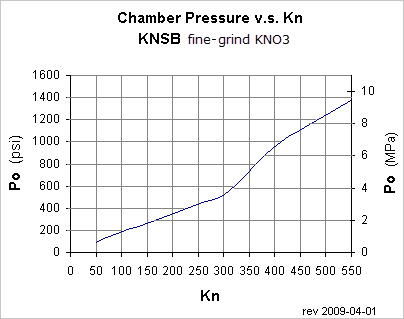
Figure 1-- Design chart for Sorbitol based propellant.
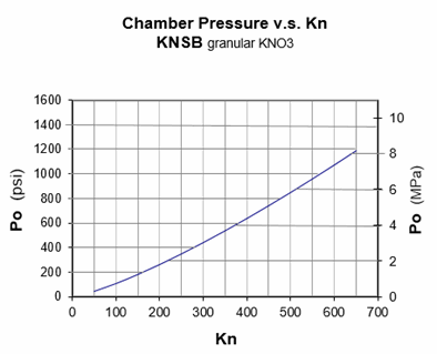
Figure 2-- Design chart for Sorbitol based propellant made with granular oxidizer.
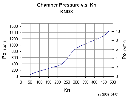
Figure 3-- Design chart for Dextrose based propellant.
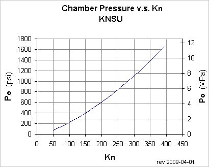
Figure 4-- Design chart for Sucrose based
propellant.
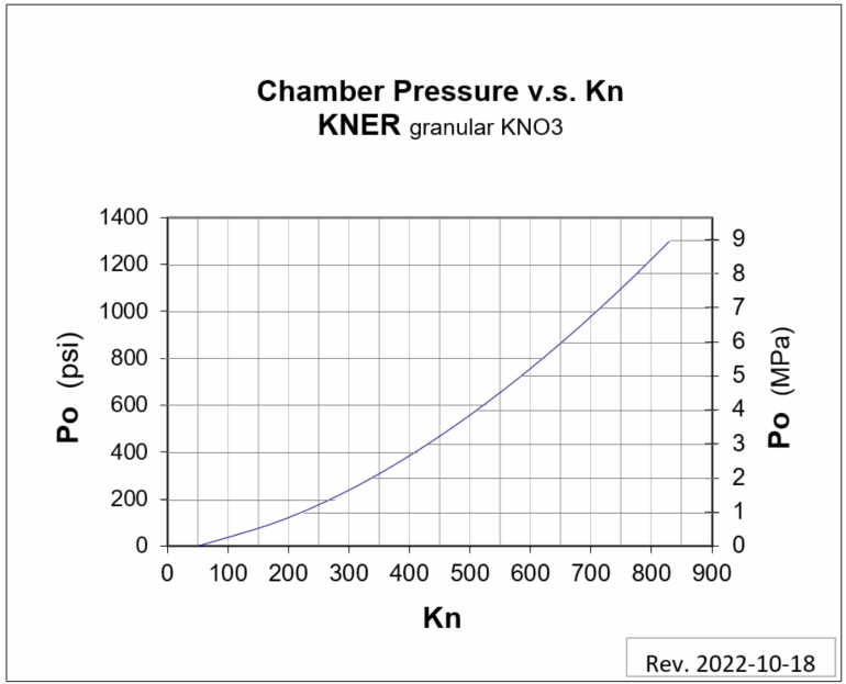
Figure 5-- Design chart for Erythritol based
propellant.
Development of Charts
The three design charts were constructed by use of the following expression for steady-state chamber conditions:

- where the parameters are defined as:
-
Po motor chamber pressure
Kn Klemmung, Kn=Ab /At (Ratio of Burning surface area (Ab) to the nozzle throat cross-section area (At) )
a Burn rate pressure coefficient
a Burn rate pressure conversion factor, MPa to Pa units (a =1 000 000n )
r propellant mass density
c* propellant characteristic exhaust velocity
n Burn rate pressure exponent
The burn rate pressure coefficients and pressure exponents are based on
experimental Strand Burner measurements. Details are provided in the KN-Dextrose & KN-Sorbitol Propellants -- Burn Rate Experimentation
web page. For KNSU, the values used were a=0.0665 in/sec (8.26 mm/sec)
and n=0.319, with these values obtained from an earlier series of Strand
Burner measurements.
The characteristic exhaust velocity is
calculated as shown below. The applicable parameters for each propellant
type are given in Tables 1-3:

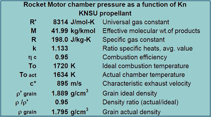
Table 1
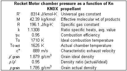
Table 2

Table 3
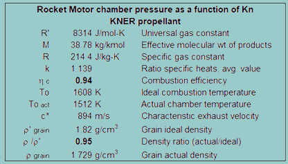
Table 4
Determination of Kn
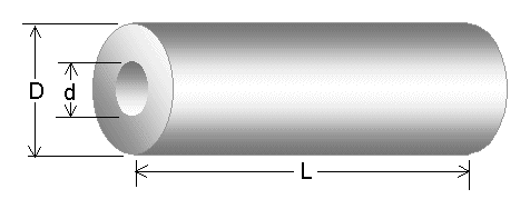
Figure 4-- Hollow cylindrical grain
The burning surface area for a hollow-cylindrical grain, as shown in Figure 4, may be calculated as follows:
- Grain with unrestricted burning (no surfaces inhibited):
-
Ab max = Ab initial = ½ p (D 2 - d 2) + p L (D + d)
-
Ab final = p (D + d) (L - t) where t = ½ (D - d)
Grain with outer surface inhibited (burning at core and ends):
Ab max = Ab initial = ½ p (D 2 - d 2) + p d L
Ab final = p D (L - 2t)
Grain with both ends inhibited (burning on outer surface and core):
Ab = constant = p L (D + d)
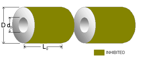
Figure 5-- BATES grain
A BATES grain configuration is shown in Figure
5. This usually consists of two or more propellant segments, inhibited
on the outer surfaces. This configuration is typically used when a
nearly neutral Kn profile is desired (red curve in Figure 6). Kn slope
rises to a maximum value then decays. The shape of the curve is
determined by the Lo/D and do/D ratios. Judicious choice of segment
length and core diameter is necessary, or else the Kn profile may
instead have only a progressive profile (green curve) or regressive profile (blue curve). Ideally, Knmax should occur at a surface regression of one-half the web thickness, to produce a symmetric profile (initial Kn = final Kn).
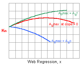
Figure 6-- BATES Kn profiles
The instantaneous grain burning surface area is given by:
Ab = N [½ p (D2 - d2) + p L d] (Eqn.1)
where N is the number of segments; d and L are the instantaneous values of core diameter and segment length, and are given by:
d = do + 2x
and L = Lo -
2x (Eqns.2a,
2b)
where x is the linear surface regression (distance the web has
burned, normal to the web surface). This is illustrated in Figure 7. The
dashed lines represent the geometry of the burning surfaces at some
arbitrary point of surface regression.
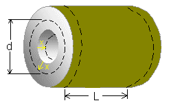
Figure 7-- BATES grain illustrating regression of the web
The initial and final burning surface areas are given by:
Ab initial = N [½ p (D2 - do2) + p Lo do]
Ab final = N p D (Lo - 2t) where t = ½ (D - do)
The value of x when the burning surface area reaches maximum is important as this determines maximum chamber pressure. This value of x may be found by setting the derivative (represented by the slope of the Kn v.s. web regression curve) to zero (i.e. dAb/dx = 0), then solving for x.
- As such, the value of x is found to be:
- x = 1/6 (Lo - 2do) at Ab max
The value of Ab max is then found by substituting x into Eqns. 2A and 2B to find d and L, then substituting these values into Eqn. 1.
Note that the Kn profile is progressive if the calculation gives x > do. In this case, Ab max = Ab final
The Kn profile is regressive if the calculation gives x < 0. In this case, Ab max = Ab initial
- When designing a rocket motor, the dimension D is usually limited by factors such as casing or fuselage size. The choice of core diameter, do,
is usually based upon desired web thickness (which determines burn
time) and erosive burning considerations. Thus, segment length, Lo, is the parameter that may be available to control the Kn profile. The value of Lo may be found which gives a symmetric Kn profile (initial and final Kn are equal), if D and do are specified:
- Lo = ½ (3D + do) for symmetric profile
The "flatness" of the curve, which is always concave downward,
is dependant upon the do/D ratio. As do/D approaches unity, the
concavity approaches a straight line.
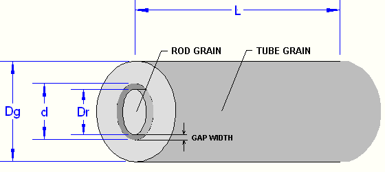
Figure 8-- Rod & Tube grain
The burning surface area for a Rod & Tube, as shown in Figure 8, is completely neutral (does not change during the burn) and may be calculated as follows:
Ab =p (d + Dr) L
However, the diameter of the Rod Grain needs to be equal to twice the
web thickness of the Tube Grain in order for this to be strictly true.
This ensures that burnout of the Rod Grain occurs simultaneously to that
of the Tube Grain.
Dr = (Dg - d)/ 2
As well, the following surfaces are inhibited from burning:
- Tube Grain outer surface
- Tube Grain ends (both)
- Rod Grain ends (both)
The gap width should be chosen such that the initial port area (Ap) is a
minimum of 2 times the nozzle throat cross-sectional area (At).
Ap > 2 At or
p /4 (d2 - Dr2) > 2p /4 Dt2 (where Dt is throat diameter).
or,
(d2 - Dr2) > 2 Dt2
Example of Usage
- Example 1
-
Determine the initial, maximum, and final steady-state chamber pressure for an unrestricted hollow cylindrical grain of KNDX with the following dimensions:
- Outer diameter 2.25 inches
- Core diameter 1.00 inches
- Grain length 10.50 inches
The nozzle throat diameter is 0.650 inches.Solution:
Ab max = Ab initial = ½ p (D 2 - d 2) + p L (D + d)
This gives Ab max = Ab initial = ½ p (2.25 2 - 1.00 2) + p 10.50 (2.25 + 1.00) = 114 in2
-
Ab final = ½ p (D + d) (L - t) where t = ½ (D - d)
Therefore t = ½ (2.25 - 1.00) = 0.625 in.
and Ab final = p (2.25 + 1.00) (10.50 - 0.625) = 101 in2
The nozzle throat cross-sectional area is: At = ¼ p (0.650)2 = 0.332 in2
This gives an initial, and maximum, Kn = 114 / 0.332 = 343. The final Kn = 101 / 0.332 = 304.
From Figure 2, the initial and maximum steady-state chamber pressure is found to be 1080 psi. The final steady-state chamber pressure is 950 psi.
- Example 2
-
Determine the initial, maximum, and final steady-state chamber pressure for a BATES grain configuration of KNSB with the following dimensions:
- Outer diameter 75 mm.
- Core diameter 22 mm.
- Segment length 100 mm
- 3 segments
The nozzle throat diameter is 13 mm.Solution:
- The value of web regression, x, at the point of maximum chamber pressure is found from the following expression:
- x = 1/6 (Lo - 2do)
Therefore, x = 1/6 [100 - 2(22)] = 9.33 mm
Substitute the value of x into the following equations:
d = do + 2x and L = Lo - 2x
Giving d = 22 + 2(9.33) =40.7 mm and L = 100 - 2(9.33) = 81.3 mm
Substitute the values of D, L and d into the equation for burning area: Ab = N [½ p (D2 - d2) + p L d]
Giving Ab max = 3 [½ p (752 - 40.72) + p (81.3) 40.7] = 49 890 mm2
-
The initial and final burning surface areas are given by:
Ab initial = N [½ p (D2 - do2) + p Lo do]
Ab final = N p D (Lo - 2t) where t = ½ (D - do)
This gives:
Ab initial = 3 [½ p (752 - 222) + p (100) 22] = 44 960 mm2
Initial web thickness is t = ½ (75 - 22) = 26.5 mm
And Ab final = 3 p 75 [100 - 2(26.5)] = 33 220 mm2
The nozzle throat cross-sectional area is: At = ¼ p (13)2 = 133 mm2
The initial, maximum and final Kn can now be calculated:
Kninitial = 44 960 / 133 = 338
Knmax = 49 890 / 133= 375
Knfinal = 33 220 / 133= 250
From Figure 2, the maximum steady-state chamber pressure is found to be 6.3 MPa. The initial and final steady-state chamber pressure is 5.0 MPa and 3.1 MPa, respectively.
Example 3
A rocket motor with a BATES grain configuration of KNDX is to be
designed to give an approximately neutral burn profile, with matching
initial and final Kn values (producing the maximum Kn midway through the
web regression). For the following segment and core diameters, what
length should the segments initially be?
- Outer diameter 50 mm.
- Core diameter 18 mm.
- 4 segments
- Solution:
-
Lo = ½ (3D + do)
This gives Lo = ½ [3(50) + 18) = 84 mm.
Verify that initial and final surface areas are identical:
Ab initial = 4 [½ p (502 - 182) + p (84) 18] = 32 673 mm2
Ab final = 4 p 50 [84 - 2(16)] = 32 673 mm2 where t = ½ (50 - 18) = 16 mm

Originally posted May 18, 2001
Last updated October 19, 2022
Return to Top of Page
Return to Home Page


