|
|
|
|
The launching system that I used for my amateur rockets was based largely on the system that I had used earlier for my model rockets. For example, the launcher. For my. model rockets, I used a wooden launch pad supported by adjustable tripod legs. The launch rod, which guided the rocket during the first few feet of flight, was an 1/8 inch aluminum rod, 3 feet in length. The model rocket was fitted with a pair of launch lugs glued to the fuselage side, which slid along the rod.
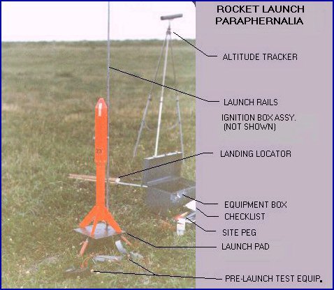
For my amateur rockets, the launcher was constructed of a steel base with adjustable tripod legs. The launch rod consisted of three 1/2 inch (1.27 cm) diameter steel tubes that fitted together (like tent poles), with a combined length of 8 feet (2.44 metre). At first I had used solid steel rod, but found that it was a little too "whippy" (because of the mass). Thin-walled steel tubes are less prone to this because they are lightweight.
The rockets were fitted with launch lugs, but rather that using a single pair of upper and lower lugs (as I had for the model rocket), I used a pair of lugs on two opposing sides of the rocket, to provide for a more balanced drag load, to minimize veering of the rocket during its ascent. Each lug consisted of a short length of aluminum tube, of 3/4 O.D. (large enough to eliminate the possibility of binding on the launch rod).
Although this launcher system was rather simple, it served me well. It was very portable and easy to set up and adjust. Since my rockets had very high acceleration off of the launch pad, this simple method of initial guiding of the rockets functioned satisfactorily, thus I never saw the need to improve upon it. The only drawback of possible significance was the aerodynamic drag due to the lugs. However, further investigation into this revealed that reduction of max. altitude, for rockets of my particular configuration, was not significant.
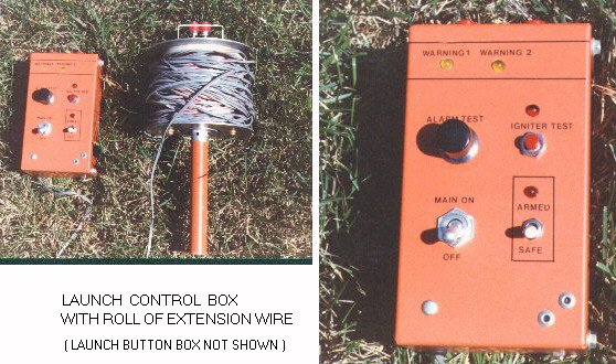
The Launch Control Box is equipped with 4 AA nicad (rechargeable) batteries, providing a 5.2VDC power source. This supplies power for the engine igniter, as well as the control circuitry. The circuit allows for a pre-launch continuity check of the engine igniter by passing a small (25mA) current through, utilizing an LED indicator for confirmation.
Safeguards are built into the system to eliminate the possibility of an premature engine ignition. Three LEDs indicate various warning conditions. A blinking red LED flashes when the SAFE/ARM select switch is selected to ARM, which is normally done just prior to launch countdown. The WARN1 and WARN2 LEDs indicates if there is relay fault. WARN1 indicates closed contacts, a condition which could occur if the contacts became fused, due to (for example) a short in the igniter circuit. A 3A fuse provides redundant protection against this. The WARN2 LED indicates the condition of a shorting condition to the Launch Button Box (or the switches being both in the closed position).
Detailed instructions on how to construct a professional quality Launch Control Box. Capable of controlling up to 6 launch pads...
Launch Controller (external Link)
The method of triangulation was one of the means I used to determine the rockets' maximum altitude. This method involves measuring the angle that the rocket forms, at its peak, with respect to the ground, as seen by an observer located some distance away. This is illustrated in Figure 2, for the case of a single tracker. The tracker is a simple device that consists of a pivot mounted sighting tube fitted with cross-hairs, mounted on tripod legs (see Photo 1). From an observation point located some distance from the launch pad, the initial orientation of the tube, with the rocket sighted through the cross-hairs, is marked. After launching the rocket, the tube is rotated on its pivot until the rocket, at its peak, is sighted through the cross-hairs. The angle that has been traversed is the angle (alpha) on the diagram. Knowing the distance from the observation point to the rocket (D1), the altitude is calculated as shown.
When a single altitude tracker is used, it is best to locate the observation post at a distance perpendicular to the wind direction. This will reduce error caused by the rocket veering, which will usually be into the wind.
For greater accuracy, two altitude trackers are used (Figure 3). This will minimize error resulting from the rocket veering. The observation points are located at opposing sides of the launch pad. Ideally, the observation points should be located directly upwind and downwind. The altitude of the rocket can be taken as the average of the two measurements, or can be more precisely calculated by the formula shown in Figure 3. The lateral drift (D) can be calculated, as well.
As a rule of thumb, the base distance from the launch pad to the observation point(s) should be equal to the expected peak altitude. This will result in a measured angle of close to 45 degrees.
I found that the smoke cloud from the parachute ejection charge was an excellent target for sighting the peak altitude, which was clearly visible, even when the rocket was not.
I learned the hard way of how important it is to mark the exact location of rocket touchdown, by searching for hours to try to find a rocket that had been visually tracked throughout its entire flight, from liftoff to landing. The wind can carry a rocket a great distance during its descent by parachute, and from a distance, it really is difficult to judge just how far downrange touchdown occurred. So often, it was the case that my rocket was found much farther away than was thought. This is especially true if the landing area is anything but completely flat. And even more so if the area is covered with tall grass (or alfalfa, as was the case at my launch range). It doesn't take much grass to hide a rocket, lying on its side, from view!
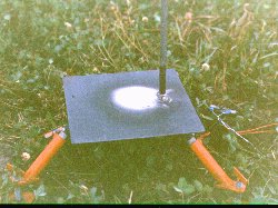
The Landing Locator is a simple, portable "pointing device" which is aligned to mark the touchdown site. Mounted on a tripod stand, it works on the same principle as pointing your finger, only difference is that once it is aligned at the moment of touchdown, it'll stay exactly aligned! The tripod legs were made to fold up, for portability, and deploy quickly. This is because it would be carried by one of the flight observers, who would chase the rocket as it descends. Just before touchdown, the tripod would be quickly set up, and the landing position marked. Such would guarantee that the rocket would be (eventually) found, no matter how far downrange it would land. This is because the search zone can be narrowed to a very fine corridor. I've even found one of my rockets, by this method, that the wind had carried far, into a wooded area. I am convinced to this day that it would not have been found otherwise!
The Distance Measuring Device is very useful for measuring distances at the launch range, such as the distance from the launch pad to the Altitude Tracker(s). Also, such a device is indispensable for measuring the distance the rocket lands downrange, which may be several hundred metres under moderate wind conditions.
The device itself is simple in concept and construction. The one that I built consisted of a 24 inch diameter bicycle wheel with an attached handle, consisting of a metal tube, mounted at the axle. A mechanical counter was mounted such that a trip arm, mounted on the spokes near the rim, would trip the counter once for each revolution. The total distance traversed is given by the expression S = pi x D x N, where D = diameter of the wheel, and N = number of revolutions. Of course, the units of S are consistent with the units of D. Or the device can be accurately calibrated by simply traversing, say, 5 revolutions, then using a tape measure to find the exact distance travelled.
The larger the diameter of the wheel, the greater is the accuracy, especially over uneven terrain.
The following is a list of items that I considered as pretty well mandatory and brought along to every launch:
The launch checklist is a list of procedures that are required to be performed, in a certain order, in preparation for the final countdown. As each procedure is performed, it is checked off the list. Having such a checklist always made for a a smoother and more efficient setup of the rocket and eliminates the possibility of forgetting some important step than could delay or jeopardize the flight. For example, "remove before launch" tags or strips of tape from the rocket. I used such a strip of tape to hold the air-speed switch flap in the flush position during transport. I learned from experience that seemingly obvious or trivial matters have a way of becoming much less so under the somewhat stressful conditions of launch preparation!
Binoculars proved to be useful for spotting the rocket once it begins to slow down as it approaches the peak of its trajectory. Prior to this, the rocket is moving too quickly for binoculars to be of any use. Once spotted through the binoculars, I found it was important to maintain visual contact, else it can be frustrating trying to "relocate" it . It is under this circumstance that it becomes apparent just how VAST the sky is!
The type of binoculars I used was Wetzlar 10x50, which seemed to be just about right for the job.
I brought along a camera to every single launch. Not only for the sake of posterity, but also to maintain a a record of details of the rocket (which varied from flight to flight), launch site, etc. The first launches were recorded using simple "instamatic" or Polaroid cameras, but soon after I invested in a good quality 35mm (Pentax ME) type, which took excellent photos even under rather low-light conditions that was the case for many of my post-sunset launches. As well, the high shutter speed (up to 1/1000th second) was great for capturing the rocket during its rapid ascent. Also, this camera gave the flexibility to change lenses quickly and easily, which was handy for photographing the different phases of the launch. For example, for photographing the rocket descending by parachute, I switched to a 135mm telephoto lens, from the 28mm wide angle lens that was perfect for photographing liftoff. For taking photos of the rocket sitting on the pad, and after touchdown, I used a standard 50mm lens.
An accessory that I occasionally used and found useful was an autowinder. This device automatically snaps a photo and advances the film, at a rate of two frames per second. This was useful for photographing the launch phase of the flight, from ignition, to post-burnout ascent.
I used a movie camera (super 8mm) to record a number of my launches. This proved to be of limited value. The quality of the pictures was quite poor, and I found the only reasonably effective way to use it was to set it up on a tripod and simply record the actual launch. It was nearly useless to handhold it, as trying to "find" the rocket in the viewfinder (despite its zoom feature) after liftoff, was futile. Video cameras were still quite new (and expensive) at the time of my last launches, so I never had the opportunity to give one a try. I am sure such would've been far superior to the super8', but it, nevertheless, would not have been a replacement for 35mm stills, with their inherent high resolution. But rather a nice complement, I'm sure.
All of my later flights were audio tape recorded. I would begin recording just prior to final countdown, giving a narration describing such things as flight number, date, time, weather conditions (temperature, wind speed and direction, visibility, etc) and other any observations that might prove to be useful later, such as problems encountered during pre-launch checkout of the rocket. At liftoff, the recorder would pick up the sounds of the engine firing. Immediately after burnout, the whining sound of the rocket could be heard, as it travelled at high speed, with this sound rapidly fading as the rocket got higher and slowed down. Several seconds of silence would follow until finally a faint "pop" sound could be heard as the parachute ejection charge fired (then cheers!). Failing that, a whining sound would once again be heard as the rocket accelerated earthward, getting louder until a final "thud" signalled impact with the ground (then groans!). This data provided, amongst other things, a permanent record of valuable data, including timing of the various phases of the flight, such as liftoff to peak time, descent time by parachute, and total flight time. This data was used together with my computer program SOAR (altitude predictor) to determine accurate altitude and velocity data, as well as aerodynamic drag data. Of course, it was necessary to take into account the sound delay resulting from the distances involved. For example, if the rocket was at 2000 feet altitude when the parachute fired, the sound of the "pop" would be recorded about 1.75 seconds later!
Since the flight observers would typically be located several hundred feet apart, it was necessary to use CB transceivers (walkie-talkies) to communicate. The ones that I used were relatively inexpensive 1/2 watt, two or three channel type. There were occasional problems with interference and reliability, but on the whole, these provided an indispensable means of communication.
Although all my launches occurred at the same general location, the specific site of each launch was usually different. The major factor that determined the exact launch site was the wind direction. I always chose the location what would give the maximum downwind range. To mark the exact location of the launch pad, I would use a site peg, which was simply a short wooden stick hammered into the ground. The exposed end was painted fluorescent orange and had (only) the flight number marked on it. The site peg was useful for a number of reasons. Perhaps the most valuable reason was in case something was discovered to be missing when I got home - such as the camera! Actually, I don't think I ever left my camera behind, but I certainly forgot my camera case once. Also, a transceiver was once left behind. Also, since many of my launches occurred quite late, I would return a day or two later to do measurements, such as the distance to touchdown site. And of course, sometimes the rockets would not be found immediately after launch, and it was necessary to return the following day to continue the search.
Last, but not least in importance, is a notepad. I always kept a detailed record of each launch, usually in the form of rough field notes which were written up more formally in a log book, after returning home. I noted such things as: date, time of launch, weather conditions including visibility, problems encountered during launch setup and rocket pre-launch checkout. Also, I noted the names of the participants and their roles (eg. observer, launcher). I also provided a description of the actual launch. For example, the following is an excerpt from the writeup on Flight C-34:
...there were some problems encountered during the pre-launch checkout of the PET-ATR circuitry. When the connector cable was removed from the rocket, the circuit triggered (twice). However, on the third attempt, the problem was overcome.
Liftoff occurred almost immediately after pressing launch button. The rocket rose very rapidly, shedding its fins, and climbed quickly out of sight. The sound from the motor was louder than usual during firing, due to the larger (C-400) motor. After about 15 (?) seconds, a "pop" sound was heard and a puff of smoke was observed from the ejection charge. This smoke cloud was quite faint due to the high altitude. I was searching through binoculars for the rocket and noticed it at this point, observing both the smoke cloud and the rocket descending by parachute, but then lost sight of it. Other observers noticed it at this point, with the naked eye, and followed its descent...."
Other details were also recorded in the log book (during rocket preparation), such as motor type, grain details (size, weight, O/F ratio, mixing duration, colour, oil bath temperature, bore size, surface defects, "fit" in motor), parachute circuit timer settings, amount of ejection charge, modifications to the rocket, pre-launch weight, etc.