Chuck Knight of Pennsylvania, U.S.A. has previously developed simple to make "G", "H" & "I" Class KN-Sorbitol rocket motors, utilizing PVC (PolyVinyl Chloride) plastic tubing for the casing and requiring no special tools for construction. This webpage features motors of the larger "J" and "K" Class, which are growth versions of the well-proven "G", "H", and "I" designs.
TOOLS
Certain tools and fixtures will be needed to facilitate the construction of the J/K motors and provide consistent results. These tools include a centering fixture, nozzle mold, and throat bushing, divergence cutter, sleeve form, casting stands and coring rods. The design and assembly of these tools follow those made for the "G", "H" and "I" motors only on a larger scale. Refer to the TOOLS
section for these motors for supplemental details and information.
A. Centering Fixture
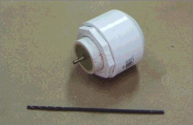
It will be necessary to drill a 1-1/4" hole into the center of a 2" PVC end cap with a fair degree of accuracy. To do this, a centering fixture is used to accurately locate a drill bit for drilling a 1/8" starter hole. This fixture uses the same centering fixture as for the "I" motor and is positioned in the 2" end cap by a 2" to 1-1/4" PVC reducing bushing. The following photograph shows how the "I" motor fixture and bushing are used.
B. Nozzle Mold
Only a light coating of the epoxy is applied to the surfaces. The epoxy glue joint creates localized hard strips within the relatively soft foam block, which can cause gouging of the soft surface as the block is being cut into a cylinder.
A 1/2" hole is drilled length way through the center of the block. The center of one of the 2-1/2" square surfaces is marked and the 1/2" brass tubing is used as a drill bit to drill the hole. Epoxy is applied to the tubing and the inside of the hole and brass tubing is inserted back into the hole so that 3" of the tubing protrudes from the foam block. The epoxy is allowed to cure.
The foam block is shaped into a cylinder by a cutting operation similar to a lathe. A drill press is ideal for the following operation, but a hand drill can also be used. The tubing and block are chucked into the drill and the drill clamped to a bench or into a vise. The drill is turned on and using the file, the corners of the block are removed and the block rounded into a cylinder. The diameter of the foam cylinder is reduced to loosely fit into 2" PVC pipe. Once the approximate size of the cylinder is reached, a sanding block is used to smooth the foam and finish the operation. The cylinder should not taper.
Note: Foam nose cones up to 4" diameter have been made using this same technique.
A mark is placed on the surface of the foam cylinder 3/4" from the end of the cylinder from which the brass tubing protrudes. The drill is turned on and an angled 45-degree surface is cut into the foam from the OD of the brass tubing to the mark. This surface will mold the convergence of the nozzle.
The block is removed from the drill. The hole is enlarged in the other end of the block and the 5/8" dowel extension rod is epoxied into the block. Painting the foam surfaces with 2 coats of epoxy to give the foam strength finishes the nozzle mold plug. When complete, the nozzle plug should loosely fit within the 2" PVC pipe. Masking tape is wrapped around the plug to give it a final snug fit to the casing when casting the nozzle.
The remaining 4 pieces of brass tubing are soldered together in a telescoping fashion to make the throat bushing. A mark is scribed or cut into the bushing 1-3/8" from the flat end of the bushing. This mark is used to position the nozzle mold in the casing.

NOZZLE MOLD PLUG, NOZZLE BUSHING, AND DIVERGENCE CUTTER
C. Divergence Cutter
The divergence cutter is made from 3/32" model aircraft plywood. An isosceles triangle with a base of 1-5/8" and a height of 3" is cut from the plywood. The tip of the triangle forms a 30-degree angle, which cuts and shapes a divergence for the nozzle of 15-degrees to the axis of the nozzle.A groove is cut across the end of a short piece of 1/2" dowel and glued to the base of the divergence cutter to make a handle. Painting with a protective finish completes the divergence cutter.
D. Sleeve Form
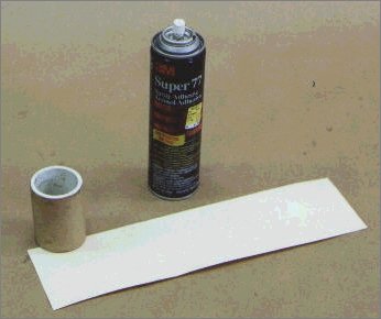
A form for rolling the inhibitor sleeves is made by starting with a 2-3/4" length of 1-1/2" Schedule 40 PVC pipe. Super 77 Spray Adhesive is sprayed onto one surface of short, 3" wide strips of Craft paper. The strips are rolled around the pipe to expand the diameter to between 1.96" - 1.97".If calipers are not available to measure the diameter of the form, the diameter can be computed from the measured circumference. A 1/2" wide paper strip is wrapped once around the form and a pin is pushed through the strip where the top layer meets the beginning of the bottom layer. The distance between the 2 puncture marks is the circumference and the circumference divided by Pi (3.1415) is the diameter. The measurement of the distance between the marks needs to be made with a high degree of accuracy. To achieve an accuracy of +/- 0.005" on the diameter, the distance between the marks needs to be measured to an accuracy of 0.015" or better than 1/64" (0.4mm). Drafting rulers have scales to 1/50", which has proven to be adequate for this application.
The final dimension for the sleeve form depends on the actual ID of the PVC pipe and thickness of the inhibitor sleeve. Several inhibitor sleeves should be rolled to verify the fit of the sleeve into the 2" PVC pipe. The inhibitor sleeve should have a sliding fit without having to be squeezed to fit into the casing.
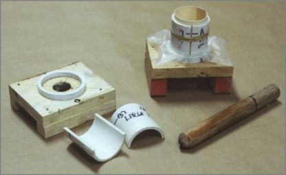
E. Casting Stands and Coring Rods
Depending on which motor(s) you plan to make it may be necessary to make 1, 2 or 3 casting stands. The casting stands are made in the same way as those for the "G","H", and "I" motors. A hole for receiving the coring rod is drilled into a wood base. A 1/4" ring cut from the end of a 2" PVC end cap or coupler is glued to the base so that the hole is directly centered within of the ring. The base is mounted on blocks so that the coring rod can be pushed through the base. Support tubes for supporting the inhibitor sleeve are cut from 2" PVC pipe. The pipe is cut into equal halves lengthwise to form a "clamshell" that can grasp the inhibitor sleeve. When the clamshell sleeve is closed around the inhibitor sleeve the edges of the halves should not touch. It may be necessary to trim one edge of one of the halves to create this opening between the halves. The 2 halves of the support tube are held together with a rubber band and will press and form the sleeve to the round interior contour of the pipe producing almost perfectly cylindrical segments. It may be necessary to wrap tape around the bottom of the support tube to provide a firm fit into the base. Coring rods are wood dowels, which have been pointed on one end. The rods are painted with a wood sealant to protect the wood against grease that is used as a release agent. The following table will provide dimensions for the 2 motors:
JK MOTOR CONSTRUCTION
Construction of the J/K motor is almost identical to the "G", "H" and "I" motors
. That is, the casing is made from Schedule 40 PVC pipe, which is enclosed on both ends by end caps. A hole is drilled through the end cap in the nozzle end to allow for the escape of the exhaust gasses. The nozzle is made of concrete in which a washer is embedded to eliminate throat erosion. There are, however, differences in the way that the grains are cast and how the motor is assembled. These variations are explained in the following section.
A. Casing and Nozzle
A single size casing and nozzle is made to accommodate both the "J" and "K" propellant grains. The casing is trimmed to final length during final assembly of the motor.
The first 1-1/2" of the inside wall of one end of the 19" PVC casing is sanded to rough the surface. The sanded area is painted with latex house paint and allowed drying over night.
A 1-1/4" hole is drilled into the center the end cap. The centering fixtures are used to drill a 1/8" guide hole, which guides the Speedbor drill bit for drilling the hole. When drilling this hole, the end cap should be held securely in a vise. Speedbor drill bits tend to grab the PVC and can torque the end cap. The end cap is glued onto the painted end of the PVC pipe using the PVC pipe cleaner and cement.
The nozzle mold is assembled. The throat bushing is slid over the end of the nozzle mold and one 9/16" washer is slid over the bushing. The J/K motor uses only 1 washer for the insert. Washers of this size have a large tolerance for the ID. It may be necessary to file or ream the ID of the washer so it slides easily over the throat bushing.
The nozzle mold assembly is slid into the open end of the casing until the scribe mark on the throat bushing is even with the outside surface of the end cap. The nozzle mold should fit snuggly and should not be able to be wiggled back-and-forth. If the nozzle mold is loose, masking tape is wrapped around the mold just below the convergence section of the mold. Enough tape is used so that the mold does no wiggle inside the casing. The 5/8" extension rod of the nozzle mold is held in a vise so the nozzle end of the casing is up and the casing rests against the top of the vise's jaws.
About 6 or 7 teaspoons of the anchoring cement is required for casting the nozzle. The slower setting anchoring cement is preferred because it allows extra time to work the cement into the nozzle cavity. Enough water is added to the cement to make the cement pourable. The cement is poured into the space evenly around and between the throat bushing and the edge of the hole until the cavity is 3/4 full. The end cap is tapped with a wood dowel to work out air bubbles and to settle the cement. Cement is added to the cavity and the end cap is continually tapped until the cavity is completely full. Excess cement is removed from the end cap.
Within a few minutes the cement will start to get firm. The throat bushing is removed while pressing down lightly on the cement with your fingers. Pressure from the fingers prevents the insert from pulling through the soft cement should the insert stick to the throat bushing. Once the throat bushing is removed, the casing is removed from the nozzle mold with a slight twisting and lifting motion.
The divergence cutter is used to cut the divergence for the nozzle. While the cement is still soft, insert the divergence cutter into the hole left by the removal of the throat bushing. The divergence cutter is twisted into the cement until the edges of the divergence cutter reach the side of the 1-1/4" hole. This produces an exit port with an expansion ratio of 4:1.
The convergence area of the nozzle is examined with the aid of a flashlight. The washer insert should be completely covered with cement and there should be no voids or cracks in the cement. If this happens, dispose of the casing and start anew.
Allow the cement to cure and dry for at least four days.
B. Inhibitor Sleeve
The inhibitor sleeve is made from tag board cut from manila file folders. Premium file folders available from stationery stores and specified as 11 pts thickness is preferred. A strip cut from these folders long enough to be rolled twice around the form makes an inhibitor sleeve with a thickness of 0.022". If thinner tag board is used, enough layers should be rolled to make an inhibitor sleeve with a thickness of at least 0.020". Super 77 Spray Adhesive is used to glue the layers together.A problem associated with the use of file folders for the inhibitor sleeves are the folds that form the bottom of the folder. To cut a strip long enough to produce a sleeve with two layers, it will be necessary to cut across the folds. When the sleeve is rolled, the difference in stiffness between the fold and the adjoining paper can produce a bump in the surface of the sleeve that can de-laminate the layers. This de-lamination could act as a tunnel for gasses and cause the inhibitor to fail. To reduce the affect of the fold, the tag board can be pre-shaped into a rounded contour at the fold by rubbing the folder back-and-forth 15 - 20 times across a thin rod. A 5/8" dowel works very well for this procedure. The strip should be cut and rolled so that the folds are on the inside surface of the sleeve.
The tag board strips for the inhibitor sleeve are cut 1/16" (0.0625) wider than the design length of the segment. This extra length provides for shrinkage of the propellant as it cools. The extra length of the sleeve and the space left by the shrinkage of the propellant will simplify assembly of the motor. The following table gives dimensions for the tag board strips:
The inhibitor sleeve is rolled by laying the sleeve form across the tag board strip and rolling the back edge of the strip up over and under the form. The sleeve is "dry" rolled to position the sleeve form so the edges of the sleeve are even. Once the position of the sleeve form is set the sleeve is unrolled to where the back edge of the tag board just catches under the sleeve form. A light coating of adhesive is sprayed on the unrolled flat portion of the tag board strip being sure to catch the edges and the area back under the sleeve form. The adhesive is allowed to set for 20 - 30 seconds to develop a tack. The sleeve form is then finish rolled. While the sleeve is on the form, air bubbles are work out and the outside axial seam is sealed tightly. It may be necessary to secure this seam with Scotch Tape.
The inside surface of the inhibitor sleeve is painted with a primer solution of Sorbitol to aid in the adhesion of the propellant to the tag board. Enough Sorbitol is dissolved in a small amount of water until the solution achieves syrup like consistency. The solution is brushed onto the inside surface of the sleeve. The sleeves can be dried over night in a desiccator box.
C. Forward Bulkhead
A forward bulkhead is used to insulate the inside surface of the end cap from the direct heat of the burning propellant. The bulkhead is made by gluing three discs cut from pasteboard that is typically found on the back of tablets. The discs are cut slightly smaller than the outside circumference of the 2" PVC casing and should fit easily into the bottom of the end cap. Super 77 Spray Adhesive can be used for gluing the discs. One surface of the laminated bulkhead is coated with RED High Temperature RTV gasket sealant. The RTV provides a protective coating for the pasteboard. Two slits are cut into the bulkhead on opposite sides of the disc with a saw. The slits allow the passage of gasses around the bulkhead to equalize pressure and prevent the bulkhead from collapsing.
FORWARD BULKHEAD AND END CAP
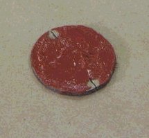
BULKHEAD
If a delay grain with ejection charge were to be incorporated into the motor, a delay grain assembly would be constructed in the same manner as for the "G", "H" and "I" motors. A 7/16" hole would be drilled into the center of the bulkhead and the bulkhead RTVed to the delay grain in the same manner as the washer.
D. Propellant Grain
The configuration of the propellant grains determines the rating of the motor. The following table gives a comparison of grain sizes:
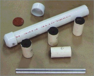
All segments for the "J" motor are of equal size. However, one segment should be clearly labeled with the word "TOP" and another segment with the word "BOTTOM".
The top 4 segments of the "K" motor are of equal size and have a core diameter of 3/4". One of these segments should be clearly labeled with the word "TOP". The bottom segment of the "K" motor has a core diameter of 7/8" and should be clearly labeled "BOTTOM".
The casting process is begun by placing wax paper over the support ring on the base of the casting stand and inserting the support tube into the ring. The wax paper covers the hole and prevents molten propellant from flowing through. The inhibitor sleeve is placed inside of the support tube to complete the preparation of the casting stand. The coring rod is coated with high temperature axle grease to prevent the propellant from sticking to the rod.
The dry batch weight of the Sorbitol and potassium nitrate (KN) is 260 grams: 91 grams of Sorbitol and 169 grams of KN. The KN is ground into a fine powder in a coffee grinder and dry mixed with the Sorbitol. The mixture is melted at 250 degrees Fahrenheit in a double boiler in which wax is the heat transfer medium. A candy thermometer monitors the temperature of the wax. Once the mixture is completely melted, it is stirred for several minutes to assure thorough blending of the KN and molten Sorbitol. When the melting and mixing of the propellant is complete it is ladled into the inhibitor sleeve.
The central core of the segment is formed with the coring rod while the propellant is still in its molten stage. While pressing down on the edge of the inhibitor sleeve, the coring rod is pushed through the propellant, through the wax paper and into the receiving hole in the base of the casting stand. Pressing on the sleeve prevents the inhibitor sleeve from riding up, as the coring rod is pushed through the propellant. The coring rod is positioned into the center of the segment and a flat stick is used to smooth and level the propellant with the top of the inhibitor sleeve. Excess propellant is removed and cleaned from around the edges of the sleeve.
The propellant needs to cool for at least 12 hours to allow the propellant to harden to permit handling of the grain segment. As the propellant cools it will shrink. The shrinkage forms a shallow cup-like depression in the top of the segment. The segments are not trimmed. The depression is used to create a gap between the segments during the assembly of the motors and eliminates the need for spacers.
For the remainder of this article, reference will be made to the "top" and "bottom" of a segment. The "top" of a segment is that end of the segment, which shows the depression from the shrinkage of the propellant. The "bottom" of a segment will be smooth as a result of being molded against the base of the casing stand.
The grain segment is removed from the support tube and the coring rod removed from the segment. The segment should be placed in a desiccator case for another 24 hours to complete the curing process.
Once all of the segments have been cast and cured, an ignition initiator of black powder is painted on both top and bottom end surfaces of each of the grain segments. Also, the inside surface of the top 1" of the core of the segment labeled "TOP" is given a heavy coat of the initiator.
Black powder may be made in the classical manner from a mixture of 75% potassium nitrate, 15% powdered charcoal, and 10% sulfur by weight. This mixture is ball milled for 12 hours to give the ingredients a thorough blending and refinement to assure a quality to the black powder that will provide rapid ignition. Seventy percent (70%) isopropyl rubbing alcohol is mixed with the black powder to make slurry for painting. The alcohol's weak surface tension provides for even mixing of the charcoal, sulfur and potassium nitrate. It also evaporates quickly. All painted surfaces are cleaned of grease before the application of the initiator.
Commercial black powder can also be used, but the granular form in which commercial powder is sold requires additional preparation. Potassium nitrate is the binder in black powder, but alcohol is not a good solvent. The addition of alcohol directly to the granular powder will only leave the black powder in a lumpy mass unsuitable for painting. To prepare the granular black powder as slurry, moisten the black powder with water. The water dissolves the potassium nitrate within the grains of the black powder and in about 10 minutes the grains begin to disintegrate into a thick paste. Alcohol is added to complete the slurry.
The painted propellant segments are dried for 24 hours or until the slurry is hard. A desiccator case comes in handy for drying the segments especially in humid weather.
This completes the preparation of the various parts of the motor.
E. Motor Assembly
The completion of the motor is accomplished by making the final trim to the casing, inserting the grain segments into the casing, and the sealing of the top end of the casing with the bulkhead and end cap. Following are photos of the lay out of parts for final assembly of the "J" and "K" motors.

The sequence in which the propellant grain is stacked is very important and the significance of the stacking sequence was explained in the design section of this article. The segment labeled with the word "BOTTOM" should be inserted into the casing first with the bottom of the segment resting against the nozzle. The unlabeled segments should be stacked next with the bottom of the segments toward the nozzle and resting against the top of the previous segment. No spacers are used. The segment labeled with the word "TOP" is stacked into the casing last with its bottom surface toward the nozzle. The depressed top surface of the segments and the bottom-to-top stacking of the segments provide the gap that permits a flow of gasses that ignite the end surfaces of each segment.
The final length of the casing is determined first. The grain segments are stacked into the casing and the distance between the top of the inhibitor sleeve of the "TOP" segment to the top of the casing is measured. One eighth of inch (1/8") is subtracted from this measurement to account for error. The resulting measurement is measured down from the top end of the casing and a mark placed on the casing. Several measurements are made to assure the accuracy of the measurement. The segments are removed from the casing and the casing is cut to its final length.
The segments are restacked back into the casing. However, before doing this, the top and bottom edge of each segment is wrapped with masking tape so the segments have a push fit into the casing. The amount of masking tape is determined by trial and error, but the fit should be tight enough so when the casing is turned upside down the grains do not fall out. The tape serves two purposes. First, it adds insulation to the inhibitor sleeve in an area, which could use some extra insulation. Second, the tight fit helps to reduce the volume of the gas flow between the sleeve and the casing that might otherwise cause problems.
It might be noted that the bottom edge of the "BOTTOM" segment nearest the nozzle may not need to be wrapped with tape. That portion of the segment rests in an area of the casing that may have been painted when preparing the nozzle. The thickness of the paint may be enough to provide a tight fit for the segment. Adding tape to the bottom of this segment may cause it to stick inside the casing and not seat against the nozzle.
Closing the top end of the motor casing with an end cap completes the motor assembly. The bulkhead is placed into the bottom of the end cap with the RTV surface facing out. The pipe and inside wall of the end cap are cleaned with PVC pipe cleaner, coated with PVC cement and fitted together. The glued joint is allowed to cure for 12 hours before the motor is ready for firing.
Installation of these motors into an airframe is similar to most other motor installations. Motor tubes can be fashioned to provide for re-useable operation of the rocket airframe. The motor tube is fitted with a thrust ring in the top of the motor tube to transfer the force from the motor to airframe. A removable spacer can be used to adjust for the difference in length between the "J" and "K" motors.
